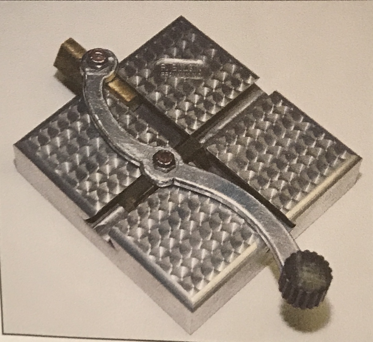
This is a toy described in J. Randolph Bulgin's "Puzzles and Peculiarities from the Machine Shop". A rotating crank moves two trapped blocks back and forth through two crossed slots. The picture below is from his book.
The first task was to determine the correct size of the device. His is approximately 4" square. He used a 3/4" dovetail cutter to cut the slot. My dovetail cutter is 1/2". Consequently, the size of the square was scaled down to approximately 2 1/2". A piece of 1/2" thick aluminum was found that is slightly smaller, so the resulting square will be close to 2 3/8". The handle itself is a little over twice that.
The other key dimension is the spacing of the holes in the crank. The ratio of this to the size of the square is 4:7. So a 2 3/8" square should have crank holes spaced 1.36" apart. This will probably be determined empirically.
My dovetail cutter is approximately 0.200" high, 1/2" wide, and the shaft thickness is 0.216". The slots will need to be made with a 3/16" end mill and widened a bit to accomodate the dovetail cutter shaft. I will need to take special care so the slots don't get clogged and deflect the end mill.
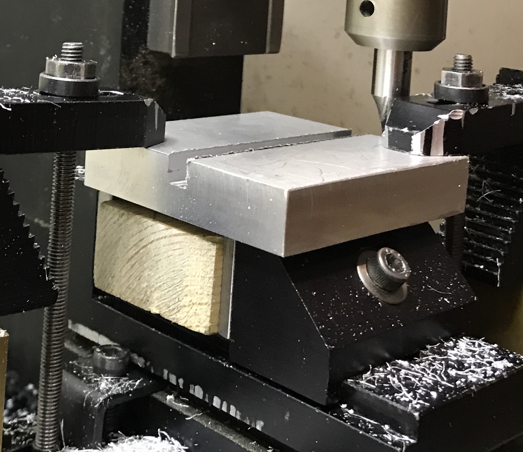
A block of aluminum was cut to approximate size with a hacksaw. This gave a rough square 2.5" on a side and 1/2" thick. The sides were squared up in the mill using the two-flute end mill in 0.005" passes. The edges were all deburred. This resulted in a 2.400" inch square.
A 3/16" end mill in good shape was not available, so a 5/32" end mill was used. The square of aluminum was clamped to the top of the vise with two strap clamps. The back edge was aligned with the x-axis within 0.001". The back edge was located and the spindle moved 1.200" to the center of one side. The slot was cut 0.225" deep in 0.015" passes. The slot was then widened 0.034" on each side. It was measured to be 0.225" wide. Holding the dovetail cutter next to the slot indicates the slot needs to be deeper. An additional 0.025" should be sufficient. The slot was cut to 0.250".
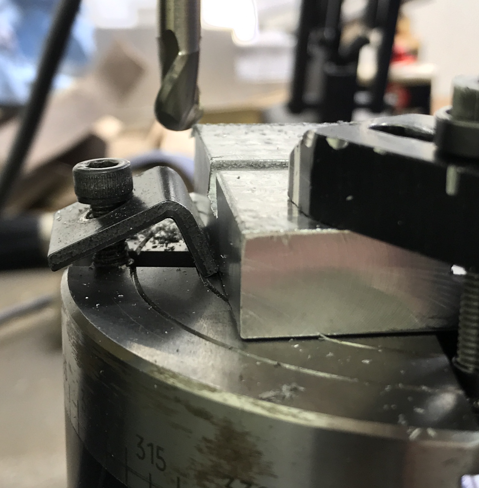
After resetting the spindle on the edge of the part, it was moved 1.200". On center the dovetail cutter was touched off on the top of the part. It was lowered 0.225". The cut was made at 0.003-0.004" per second. The cut went fine, but left a rough side, which I didn't see until the part had been removed. The part was returned to the clamps. With the cutter in the slot an adjustable parallel was used to make sure the part was parallel with the column. The cut was retaken in a climbing direction. This removed most of the roughness. A little work with a file cleaned up the sides and the burrs.
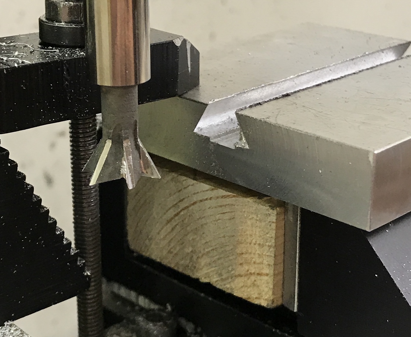
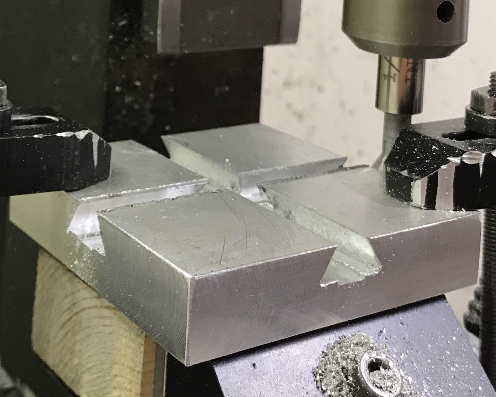
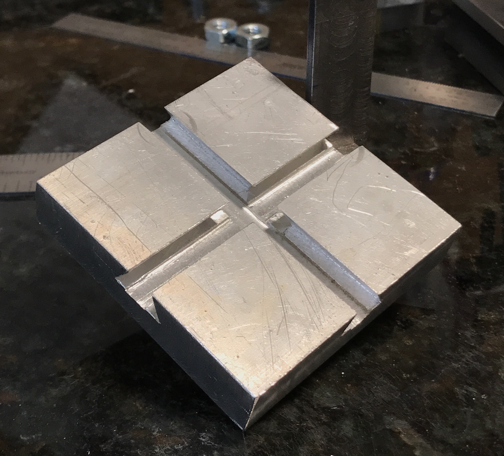
The second groove was cut the same as the first. This was followed by cutting the second dovetail. Again the process went smoothly. The dovetail was cleaned up with a small file. The photos show the completed second dovetail and the cleaned up part with crossing dovetails.
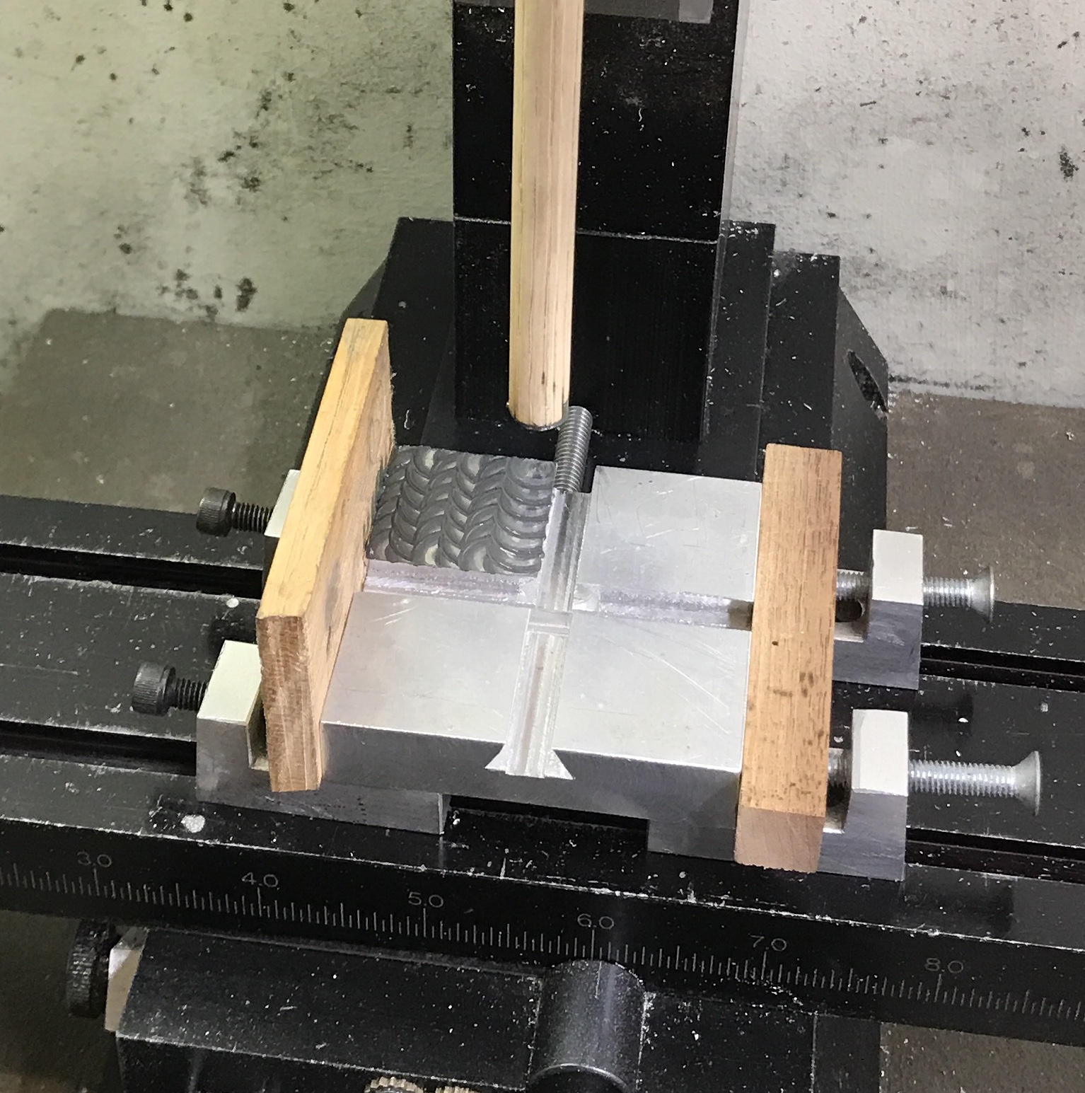
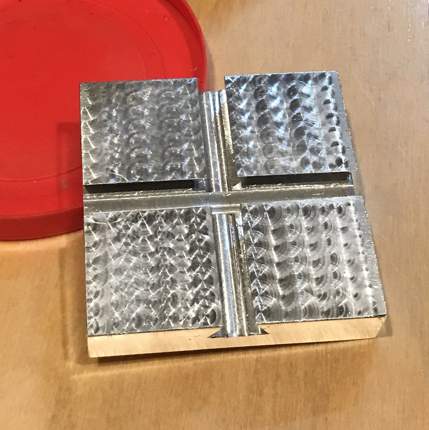
An attempt was made to jewel an aluminum scrap. Neither the aqueous solution nor the stick compound worked with a 1/4" dowel in the mill. I then tried the jeweler's rouge (red) in a drop of oil. This looked better, but was still pretty faint. Next I tried some green rouge in oil for honing steel. This looked the best and will be used to decorate this square of aluminum. The first photo shows the process and the second shows the bejeweled square. Tomorrow I will beautify the outside edges.
The base was set up on the rotary table just to provide some height. After a few failed attempts the base was aligned and clamped in place so that one side could be cut. A small strap clamp was used for the stop. The side was indicated square within 0.001". The strap clamp was set tight against the side and two clamps were used to hold the base firmly to the table. The two pictures show the setup with the second focusing on the stop.
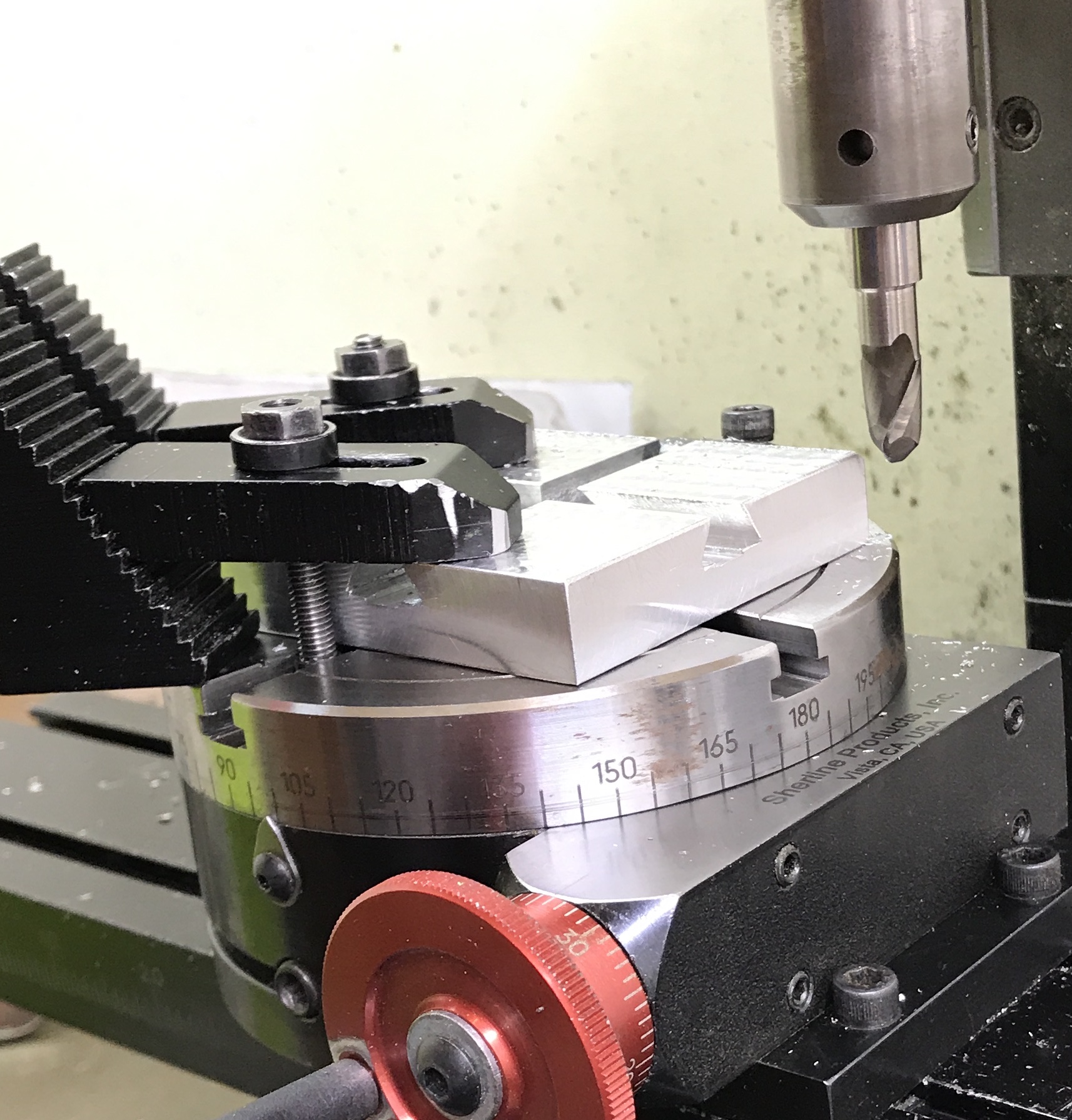
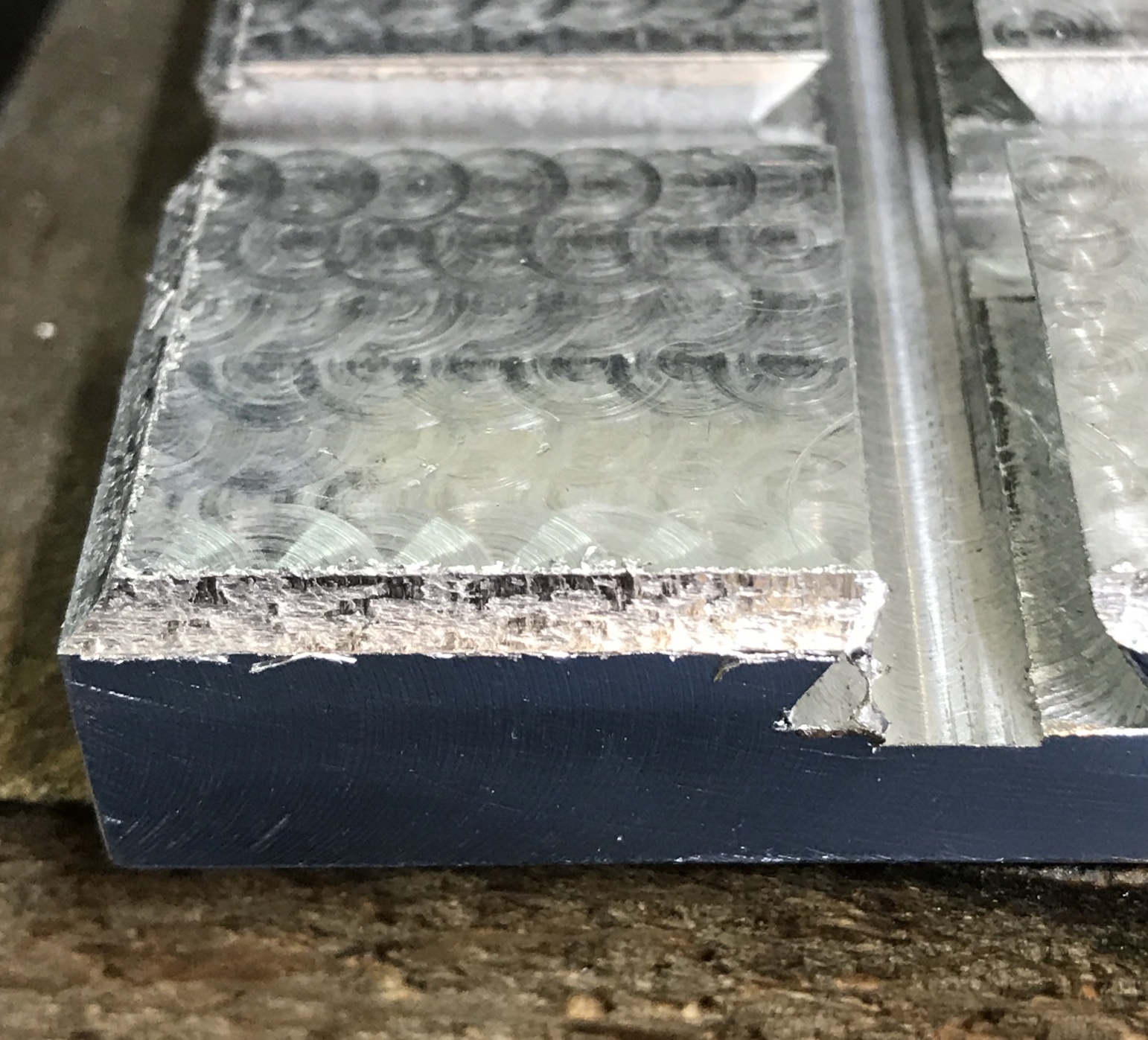
A 5/16" round end mill was used to cut the corner. The corner edge was found. Multiple cuts were taken to mill the 0.053" deep rounded groove. The part was then unclamped and an uncut side was set against the stop. This side was cut and this was repeated two more times to complete all four sides. The finish was less than desired. In each case the last cut was made using 0.003" climb milling. The poor finish can be clearly seen in the photo below. A small flat file was used to remove the burrs from the straight edges. A round needle file was used in an attempt to improve the finish of the top corners just cut.
The sliders in the picture are 3/4", while the square is 1 15/16". The scaling factor of 0.387 applied to the 2 3/8" block is 0.92". A rectangular rod of brass was found in the brass box. It is 0.50" X 0.31". A 2" length was cut off with a hacksaw. The block was held on parallels in the vise and the ends squared up. The block of brass was marked on the center line the long dimension. It was marked 0.46" in from each end. The line crossings were prick punched and punched. The brass was set up on parallels, drilled, and tapped 6-32.
A scrap of aluminum had one of the holes transferred. This hole was drilled through for a 6-32 screw. The brass block was screwed to the aluminum. The edges were aligned and the second hole was transferred to the aluminum. The aluminum was again drilled for a through hole on the transfer mark. The brass block was screwed to the aluminum plate ensuring that the edge of the brass was aligned with the aluminum. The plate was clamped in the vise jaws.
The head of the mill was set to 60.0° using the iHandy Level app. One edge of the brass was cut to a 60° angle in passes of 0.010". The part was flipped over and the other long edge was also cut to the same angle. On a number of occasions the part would shift relative to the 5/16" end mill. I could not figure out the source of the movement. everything seemed tight. I tried the part in the dovetails and it was too tight. It was reattached to the aluminum plate and returned to the vise. It was at this point that I discovered the angle had changed by 10° over the course of the cutting! The head was reset to 60° and one side of the part was cut again. The part now fit. I did not want to remove more material so one side is not a great fit in the dovetail.
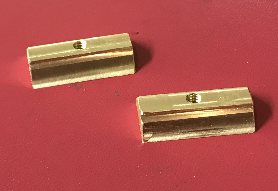
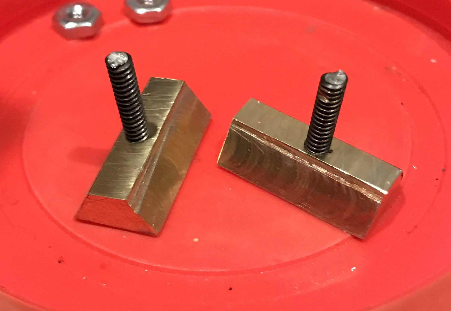
The brass was returned to the aluminum plate. It was clamped horizontally as seen in the picture below. The top was milled off to more closely match the dovetail. The part was then removed from the aluminum jig and it was cut in half with a hacksaw. Each of the parts had the new end squared and the length reduced to 0.92". The two sliders are shown the in the second photo. Some filing of the block was required to achieve smooth movement of the sliders.
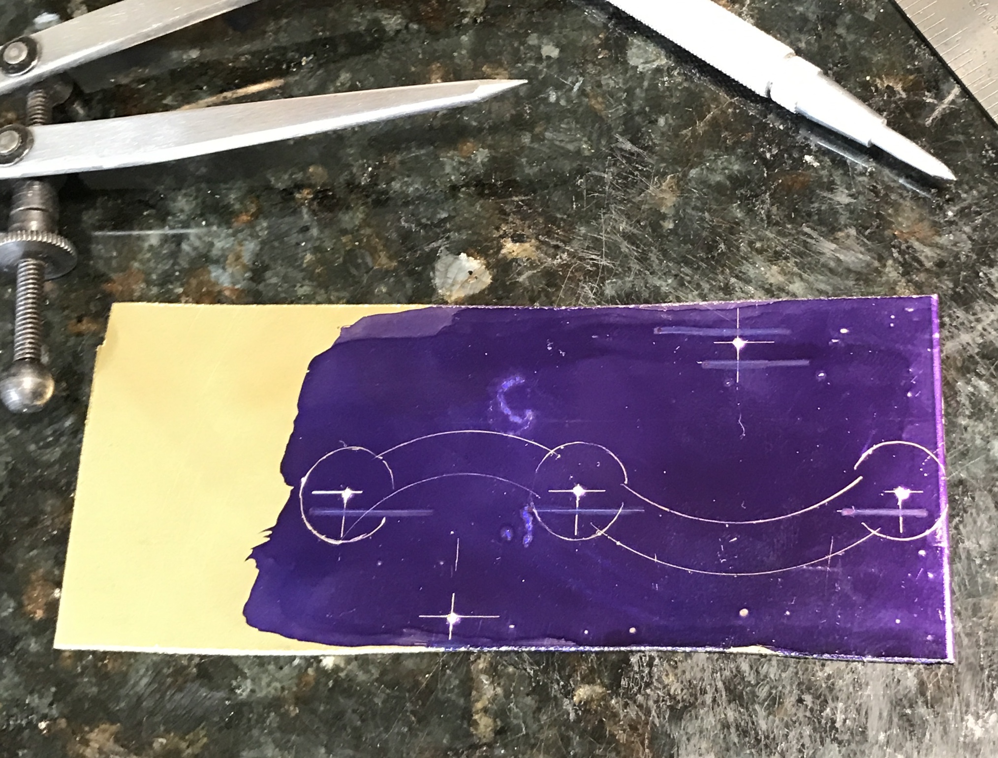
The handle needs to be 2.94" long from the hole at one end to the hole for the handle. More accurate than above, the distance between the two slider holes in the handle should be 1.24". A scrap of 1/16" brass plate was found for the handle. It will be made on the rotary table. The plate was painted with Dykem. Five hole locations were measured and marked. Three are for the screws and two are for the arcs between the screw holes. The completed layout is shown below.
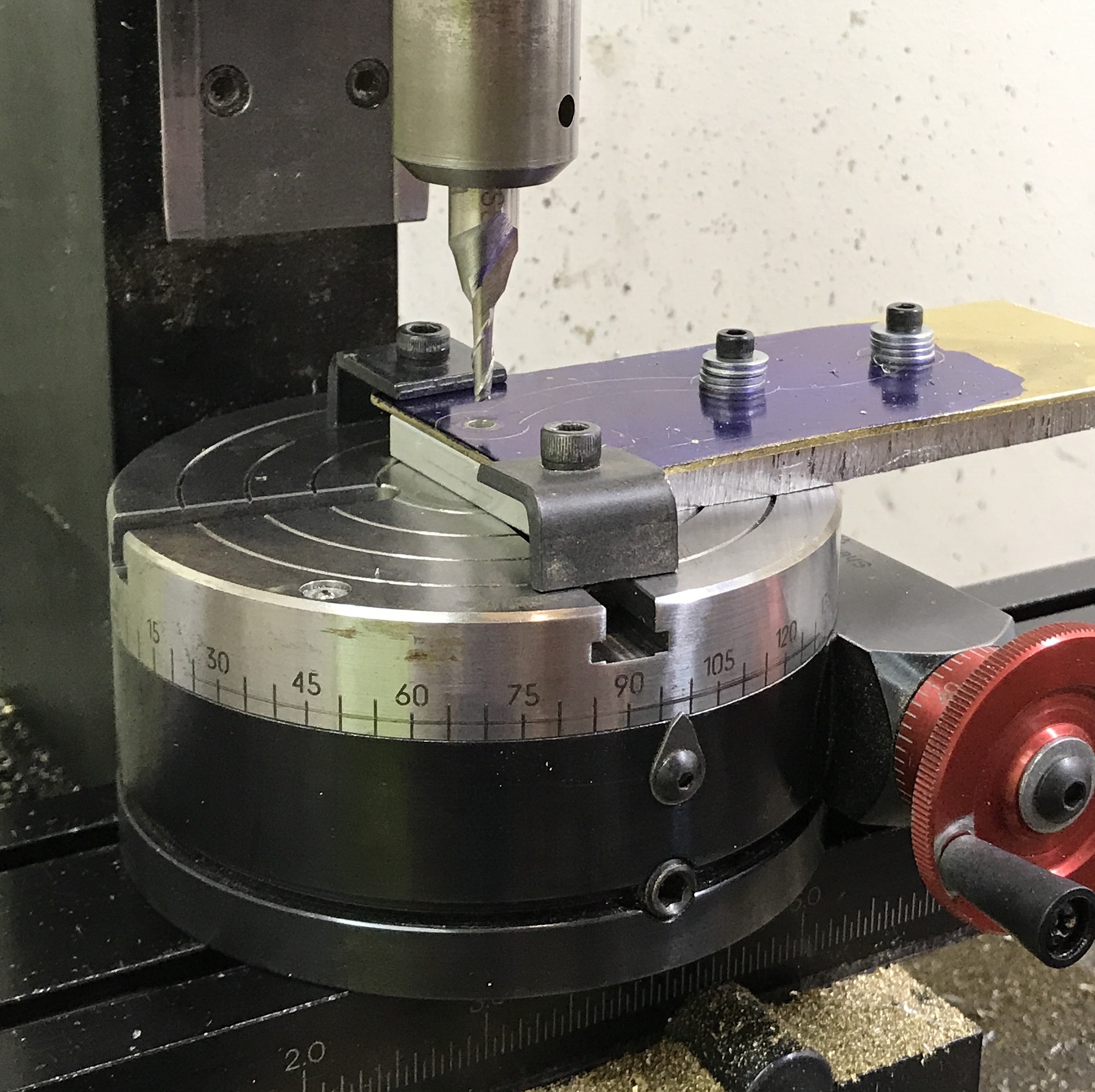
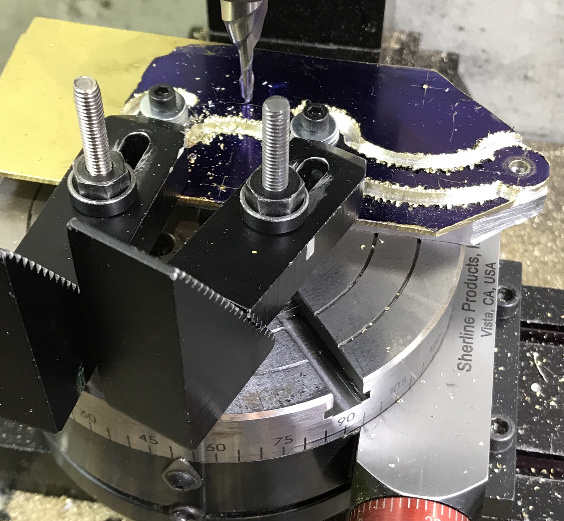
The three holes were drilled for the screws and also to fit the eventual studs in the sliders. A 9/64" drill was used. The brass plate was clamped to a 1/4" thick sacrificial aluminum rectangle about the same size as the brass plate. One hole was aligned with the drill in the spindle. The aluminum was drilled through and tapped 6-32. The plate was screwed to the aluminum and the two other holes were transferred. These two holes were drilled and tapped. The plate was then attached with two screws to the aluminum. Multiple washers were used as the screws were too long. The rotary table was set up on the mill and the spindle aligned with the center of the table. The brass plate was then clamped to the rotary table with two strap clamps. The plate was moved on the table until the spindle was aligned over the hole without a screw. This setup is shown below. The circles will be milled around the three drilled holes followed by the connecting arcs.
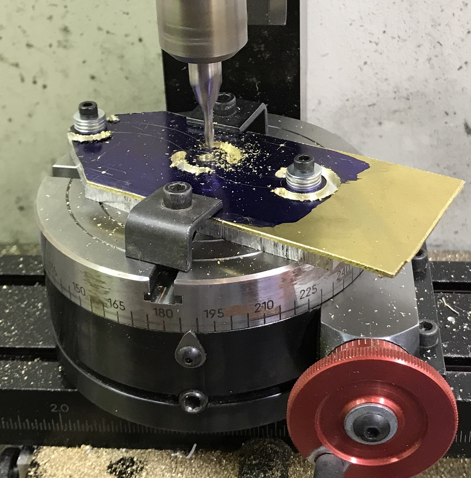
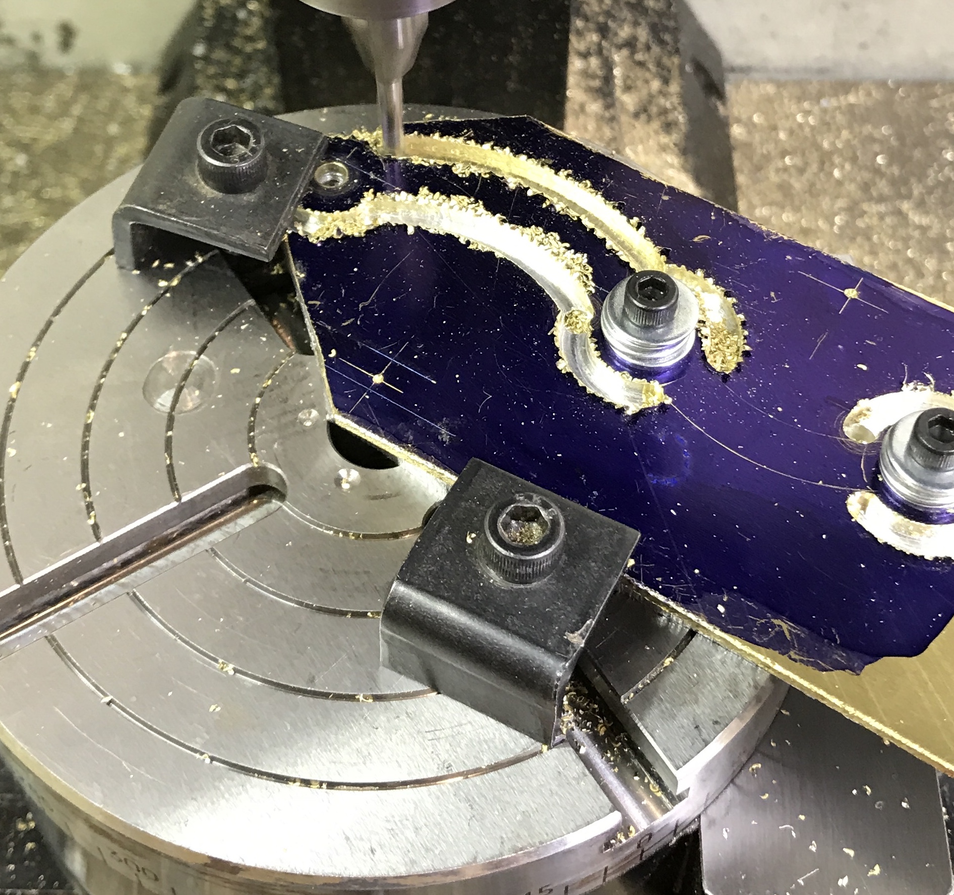
The center of the rotary table was aligned under the spindle. The part was clamped to the rotary table and the desired hole was centered under the spindle before clamping. The table was then moved 0.312" (1/4" + 1/2 of the diameter of the end mill) to put the edge of the 1/8" end mill just outside the arc.The difficult part was arranging the part on the table so the desired arc could be milled without the part running into the column. Positioning the clamps was also a challenge. Except for the arc on the edge of the brass the center and opposite end had a 1/8" hole drilled at one end of each arc. The 1/2" diameter arcs around the three holes were milled. It was necessary at one point to cut off the corners of the part and sacrificial plate in order to get a full turn.
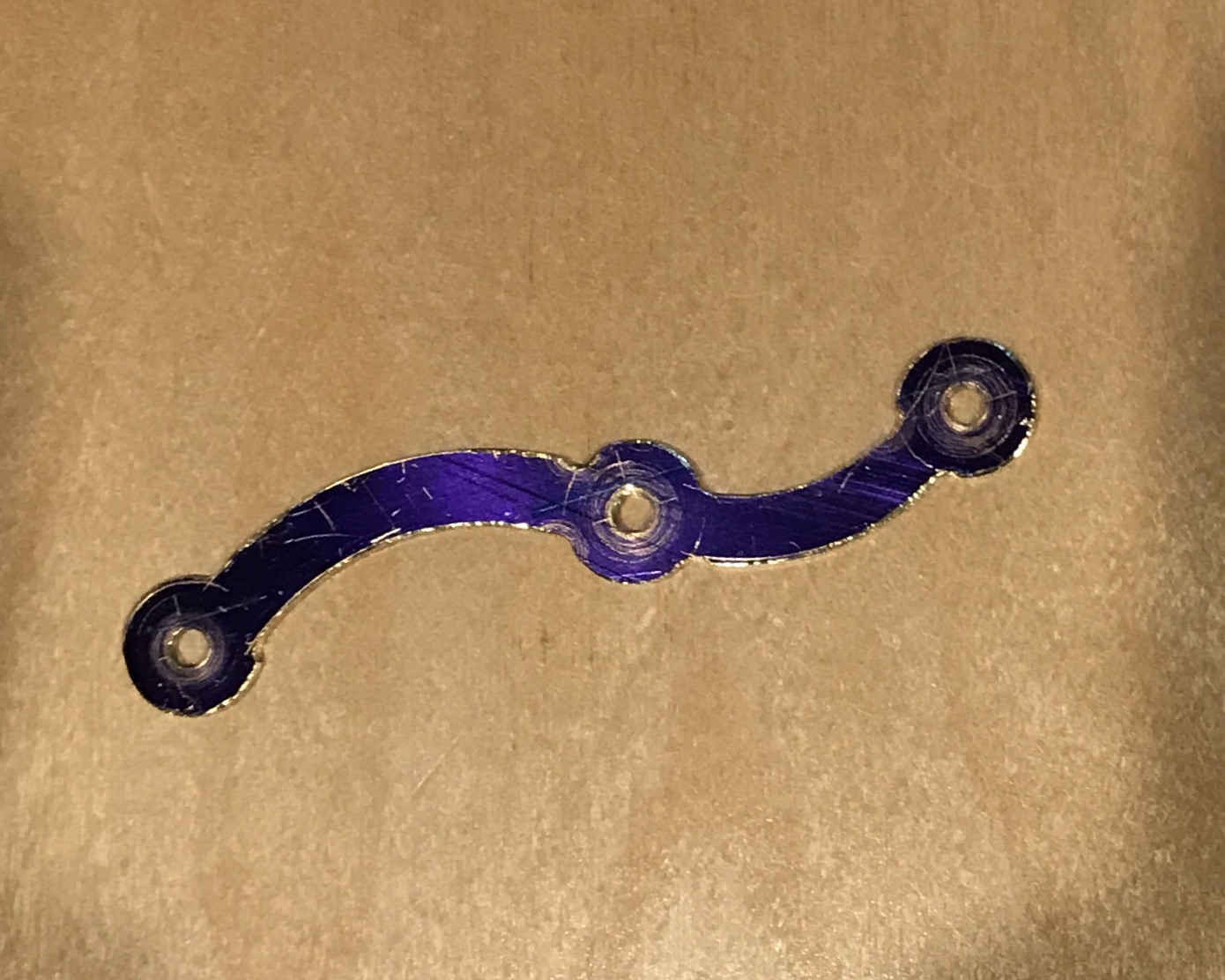
In order to mill the large arcs the part was centered over the marked center of the arc pair using the point of the edge finder. The table was moved the desired distance minus half the width of the end mill. The arc was cut from a previous arc to its neighbor. Once through the brass the second arc of the pair was cut after moving the table an additional 1/4" plus the diameter of the end mill. The final handle was removed from the aluminum plate and deburred.
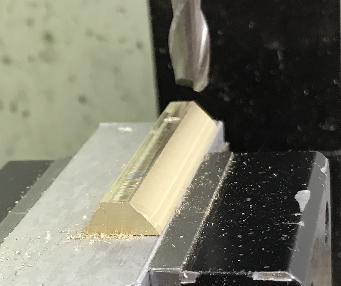
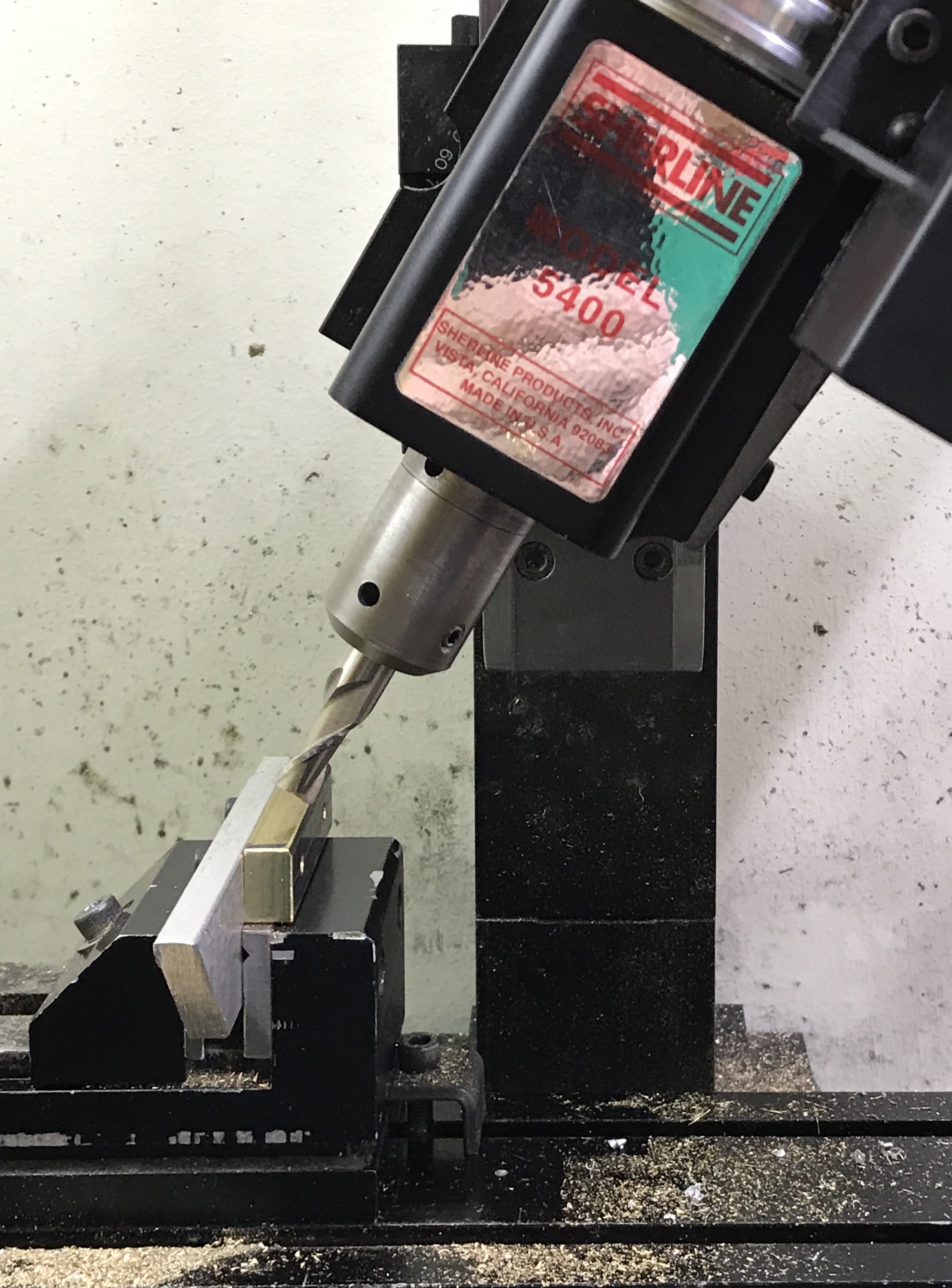
Decided to remake the sliders. A 2" length of the the 5/16" X 1/2" brass bar was cut with a hacksaw. The ends were squared up and the holes drilled and tapped as before. The holes were transferred to the 1/4" thick aluminum plate. The aluminum plate was clamped vertically in the mill vise. The spindle was set at 60° as measured by the iHandy level app. The edge of the 5/16" end mill was set outside of the edge of the brass. The spindle was lowered in 0.01" increments until the cut left a slight raised area left of the end mill. The table was then moved incrementally to the right to complete the cut. This left a raised area in the center. The photo below shows the setup. The process was repeated on the other face.
The slider was a tight fit in one groove and wouldn't fit in the other. It was returned to the mill and about 0.005" was removed. It again fit in one dovetail slot but not the other. In the slot it fit one end of the slider was tight. Back to the mill. The slider was held so one end was slightly (0.002-0.003") higher than the other. It was again milled and now it fit smoothly all the way through. The slots were measured and one was about 0.015" wider than the other. The base was set up on the mill table with a wooden block below. It was aligned using the adjustable parallel. The narrow dovetail slot was widened on one side until the slider was an easy fit.
The slider blank was cut in half with a hacksaw. The newly cut ends were faced and the lengths reduced to 0.92".
The last part to make was the knob for the handle. A blank of walnut was held in the four jaw chuck. It was drilled for a center after facing. The square blank was turned round. The spindle was set to 15° and the angled part was cut about 1/2" long. A Sherline type lathe cutting tool was used to make an deep angled cut after returning the spindle to 0°. The knob was drilled with a #36 drill and tapped 6-32. The parting tool made one groove just past the angled cut and then parted the knob off a little closer to the headstock. A SHC screw was installed and the screw held in the three jaw chuck. After a little filing and sanding to 320 grit the knob was complete.
The sanded knob was coated with shellac, sanded after two hours, and recoated with shellac. Two small spacers were made from a brass round rod. The rod was drilled with a 0.140" drill. Two 0.1" lengths were parted off and deburred. These are meant to sit under the handle and above the sliders.
The grinder was assembled and there is still a hangup as one of the sliders moves through the center open section. It gets a little crossways and the front corner catches on the dovetail opening. If the sliders were longer this might be avoided.
The hangups are caused when the slider hits the edge of the raised section next to the deeper groove made by the end mill in the center cross. I am reluctant to get rid of this relief. After some measuring the two threaded rods were cut to length. They were glued into the sliders with Loctite. The screw had a drop of Loctite put on it before threading into the wooden handle. Two nuts were locked together on the studs above the brass part of the handle. This left just a little play in the handle. It works reasonably well, with only a minimal catch. The catch can be avoided with a bit of diligence in slightly raising or lowering the handle in the correct places.